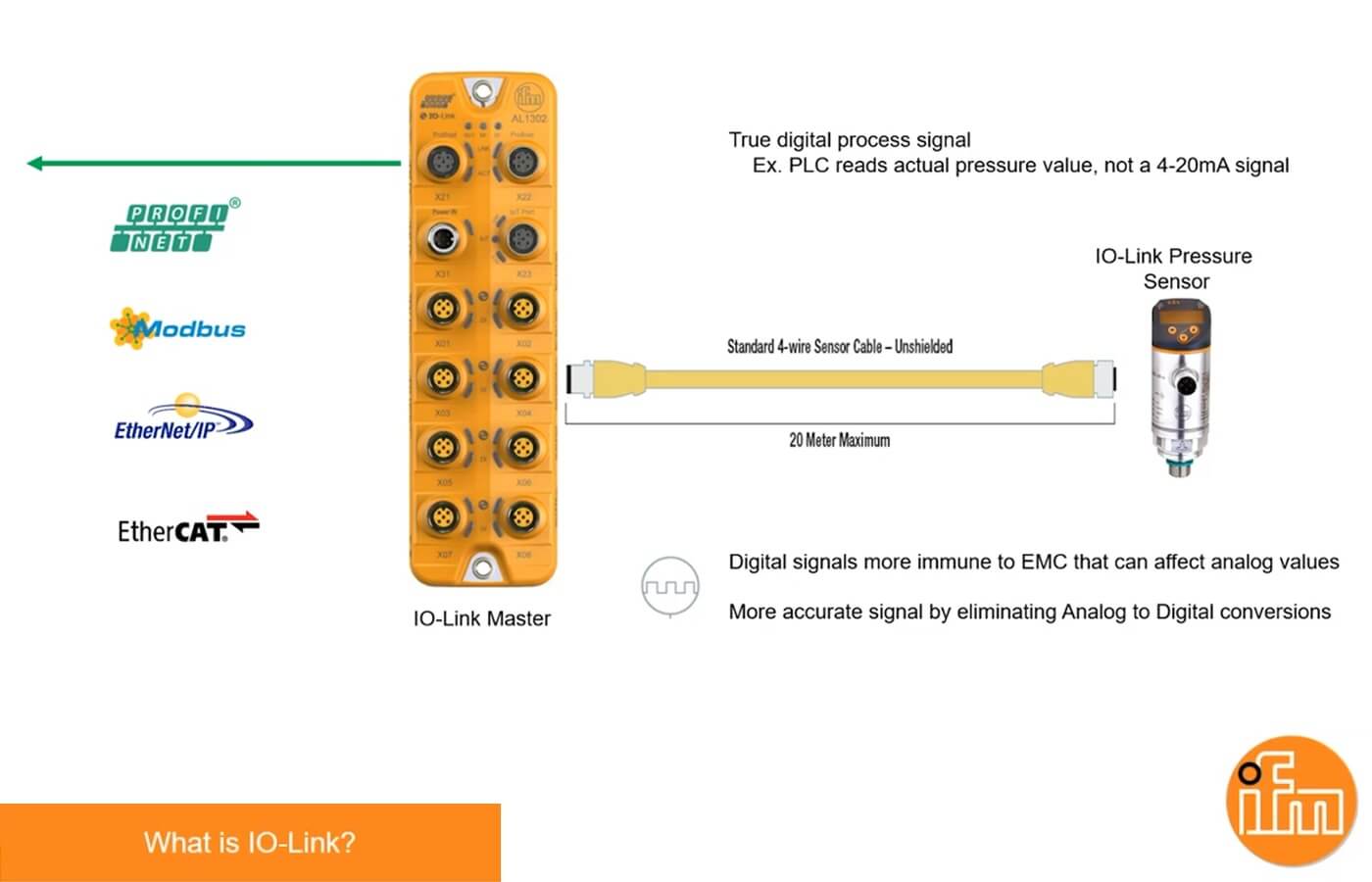
In industrial automation, unlocking rich data from sensors can transform monitoring and control. The IFM AL1326 IO-Link master integrates seamlessly with Rockwell CompactLogix PLCs via EtherNet/IP, letting you pull process values, diagnostics, and parameters from up to 8 IO-Link sensors. This short setup guide walks you through hardware, software integration, and data extraction—boosting efficiency without complexity.
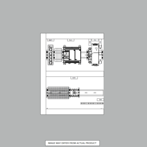
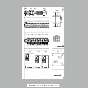
Start with basics: Mount the AL1326 in your panel or machine. Connect 24V DC power and Ethernet cable to your CompactLogix ethernet network.
Link Sensors: Plug up to 8 IO-Link sensors (like IFM’s O5 distance or SM8601 flow meters) into the M12 ports. Use standard 4-conductor cables for point-to-point communication.
Configure IP: Download IFM’s free LR Device tool (web-based). Default IP is 192.168.0.250—detect it automatically or add manually. Update to match your subnet (e.g., 192.168.1.x), write changes, and power cycle. Verify in RSLinx; a green IFM icon confirms connectivity.
This ensures the master acts as an EtherNet/IP scanner, ready for PLC communications.
In Studio 5000 Logix Designer (or RSLogix 5000), install the EDS file first:
Grab the IO-Link Startup Kit from IFM’s site (free after registration). Run the EDS Hardware Installation Tool under Tools > EDS Hardware Installation.
Select the AL1326 EDS—register it to eliminate any RSLinx warnings.
Now integrate:
Right-click your Ethernet module in the I/O Configuration tree > New Module.
Search for “AL1326,” enter the IP, and create. Set connection parameters: Input size 223 bytes, Output size 151 bytes (for 8-port config).
Download to the PLC. Go online—input tags should populate with sensor status.
Test by forcing an output; the master LEDs will blink to confirm.
The magic: IFM’s Add-On Instructions (AOIs) simplify pulling “a lot of data” from each sensor. Download sensor-specific AOIs from the startup kit (e.g., for O5 laser: 050_ID_8PORT_IOL).
Import AOI: Right-click Add-On Instructions folder > Import > Select file. Drag to a ladder rung, name the tag (e.g., Sensor_Port1_Data).
Configure: Point to the master’s input tag (e.g., Local:1:I.Data). Set Port Number (1-8), Process Data Size (default 32 bytes). Enable for cyclic process data.
Read Data:
Process Values: Get real-time metrics like distance (INT) or flow rate (REAL) directly in tags.
Parameters: Use acyclic reads for settings (e.g., switchpoints) via AOI parameters like ParamIndex.
Events/Diagnostics: Monitor faults, quality signals, or vendor IDs—AOIs flag errors and expose events for alarms.
Example: For an O5 sensor on Port 1, the AOI outputs distance in mm, plus temp and signal strength. Scale in PLC logic for HMI display. Run the routine every scan for live updates.
Pro Tip: For multi-sensor setups, use a generic 8-port AOI; it handles arrays for bulk data.
With this IFM AL1326 IO-Link master CompactLogix setup, you’re set to harvest diagnostics and process data that analog sensors can’t match—cutting downtime and optimizing processes. Total time: Under an hour for pros. Apply these steps in your PLC setup today! Visit the AL1326 webpage for more details. Let Automation Ready Panels design and program your next PLC control system today! Contact Us